CWU Mini-Baja Car 2015-16
Michael Cox MET SEnior Project 2015-16
Analysis
. Approach: Proposed Sequence of analysis:
The following proposed sequence of analysis will be a guide in the process of analyzing the project.
-
Use energy analysis to determine forces applied to suspension system at a max height drop.
-
Use equations of equilibrium to determine forces applied to leaf spring in suspension system.
-
Use cantilever beam analysis to determine geometry and travel of leaf spring.
-
Use Solidworks assembly to determine that there will be no interference between components of either steering or suspension systems.
-
Use Solidworks to analyses and evaluate stress concentrations in A-arm.
-
Apply shear flow analysis of fasteners to determine safety factor to shear.
-
Determine drive angles of vehicle to complete a 50” radius turn.
-
Determine Ackerman angle using geometric analysis.
II. Analysis of Suspension
The first step in analyzing the suspension was to determine the amount of force the leaf spring needed to carry to support the vehicle. It is expected the completed weight of the vehicle will be 4 lbs., and it will be supported by four tires. Due to the fact that the vehicle will land on one wheel prior to the others the leaf spring will be analyzed supporting the whole weight of the vehicle on one tire. This force was determined to be 128.8 pounds (analysis in Figure 8).
After determining the force applied to the wheels, a static analysis was performed to determine the force applied to the leaf spring was 88.702 lbs. (static analysis Figure 9). At that point a material was chosen for the leaf spring, the material selected was AISI 1095. This material was chosen because it is easy to acquire and the modulus of elasticity is 29000 ksi, which makes it a good steel for a spring.
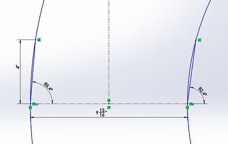
Once material was selected the dimensions for the leaf spring needed to be determined. The cantilever beam equation was used to determine the final dimension (width) by inputting thicknesses that were available for purchase, the final dimensions of the spring were determined to be 2.65”x1.98”x.042” . (Cantilever beam and dimensions Figure 10)
As per competition standards a standard fastener will be used, the #6 phillips pan head machine screw was chosen because we have many of them and they are free. In prior years a source of failure for 1/10th scale Baja cars has been shearing of the fasteners that connect the suspension frame together. To avoid this a shear analysis was completed on the #6 machine screw fasteners that will be used in the construction of the vehicle. Based on the assumption that the leaf spring and the tires fail to absorb any of the impact the fasteners in the A-arms will have to be able to withstand the 64.4 pounds of force applied to their cross-sectional area. Through a shear analysis it was determined that the machine screws has a 9.65 safety factor when experiencing this load (for fastener analysis see Figure 11)
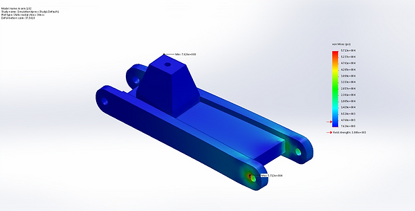
To determine the structural capacity of the A-arms a finite element analysis is necessary due to the complex geometry of the part. The first step in this process was to approximate the maximum force the part will have to endure. Given the vehicles estimated weight of 4lb. and an estimated top speed of 20 mph. if the vehicle impacts a wall and the force of impact is split into the two front wheel components the force that a single side receives is 586 lbs. (for analysis see Figure 12). But being that the vehicle will is designed only for top speed burst in slalom, cruising speed (10 mph) is the estimated speed for negotiating the obstacle course, so the force will be reduced to 292 lb. force..
To increase the accuracy of the Solidworks F.E.A. of the a A-arms material data was gathered for printed ABS plastic via matweb and through course work (MET 418 Printed Material Spec Sheet). The first design iteration A-arm 1.01 (Fig. 1) failed, it yielded in multiple locations and had a minimum safety factor of .05. (Full detailed F.E.A. reports on all tested parts in Appendix H FEA (Finite Element Analysis Reports).III. Analysis of Steering To retro fit last year’s steering components properly a geometric analysis was done to determine the new angle of the steering arm components. Adjustments were made to components and the steering angle was determined to be 73 degrees. To determine Ackerman angle another geometric analysis was applied via Solidworks to determine difference in angle between the two tires during a full turn. Attempting a turn approximately 8ft in diameter requires the inside wheel to have a difference of angle of .6 degrees. This value was smaller than initially anticipated, so another analysis was done to determine the difference between angles in a much smaller turn (25” radius). The results indicated that only a 3 degree change to the inside tire needs to be made. This can easily be accomplished due to the fact that the threaded rods that the steering linkage is comprised of are adjustable in length. This will provide a turning radius that should be well under the required 50” in radius turn. (Ackerman analysis provided in Figure 17, Figure 18, Figure 19, and Figure 20)
Static Analysis


Dynamic Analysis


Suspension Analysis

Steering Analysis

Finite Element Analysis (FEA)